
How Do You Optimize Efficiency and Load Handling in Parallel-Shaft Mechanical Systems with Spur Gears?
Mechanical drive systems across industrial automation, automotive machinery, and material handling equipment require positive, high-efficiency power transmission. When transferring motion between parallel shafts, spur gears remain the most widely used and reliable solution. Understanding their geometric principles, material selection criteria, and tooth finishing processes allows engineers to maximize load capacity while minimizing wear.
What Is a Spur Gear and How Does Straight-Tooth Geometry Transfer Power?
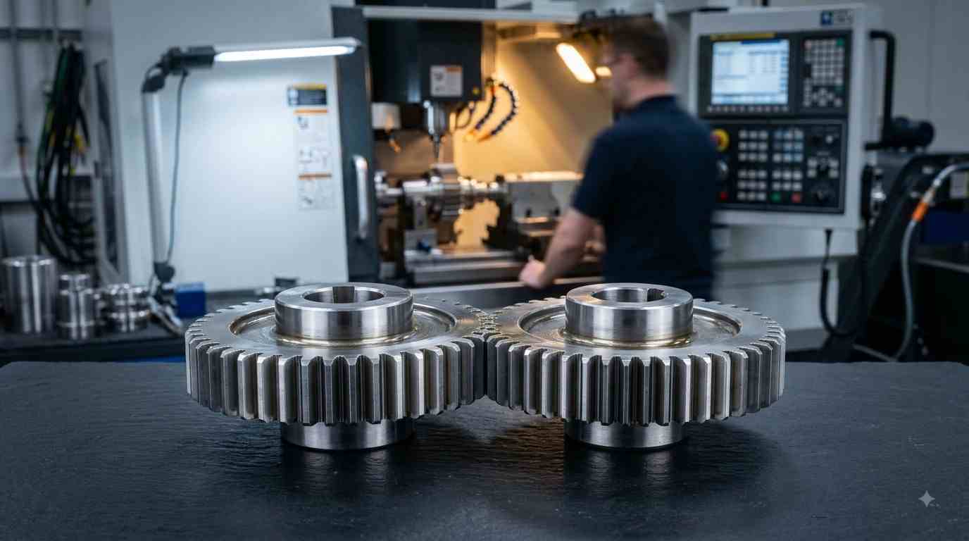
A spur gear is a cylindrical mechanical component featuring straight teeth cut parallel to the gear's axis of rotation. Mounted on parallel shafts, mating spur gears mesh together to transfer rotational motion and torque from a driving shaft to a driven shaft.
Because the teeth engage across their entire face width simultaneously, spur gears deliver a direct, 1-to-1 power transition per tooth cycle. This geometric simplicity offers outstanding mechanical efficiency—often reaching 98% to 99% per gear mesh stage—because minimal power is lost to sliding friction compared to worm or bevel gear sets.
Key Mechanical Advantages of Spur Gears in Industrial Drives
-
Zero Axial Thrust Load: Unlike helical gears, which generate longitudinal side-thrust forces along the shaft, spur gears exert purely radial loads on support bearings. This simplifies housing designs and reduces bearing wear.
-
High Operational Efficiency: The direct line of engagement limits frictional losses, making spur gears ideal for high-efficiency energy transfer.
-
Ease of Manufacturing and Maintenance: Straight-tooth geometry allows straightforward gear hobbing, shaping, and inspection, resulting in cost-effective production and straightforward maintenance.
-
Compact Gear Ratios: By varying the pitch diameter and tooth count between the pinion and driven gear, engineers can achieve precise speed reduction or torque multiplication within a compact footprint.
Key Design Parameters: Module, Pitch Diameter, and Pressure Angle
Designing an efficient spur gear assembly requires precise calculation of key geometric variables:
-
Module (or Diametral Pitch): Indicates the size of the gear teeth. Mating gears must have the exact same module to mesh properly without binding or excessive play.
-
Pitch Circle Diameter (PCD): The theoretical operating circle where two meshing gears make contact. It dictates center-to-center shaft distance and velocity ratios.
-
Pressure Angle: The angle between the tooth force vector and the pitch line (standardized at 20 degrees or 14.5 degrees). A 20-degree pressure angle increases tooth root strength, allowing higher load capacity and reducing tooth bending stress.
Material Selection and Gear Tooth Precision Finishing
Spur gear performance depends heavily on matching material properties to operational load profiles:
-
Steel Alloys (4140, 8620, 20MnCr5): Ideal for heavy-duty power transmission. Case-hardening (carburizing) or induction hardening creates a wear-resistant surface shell while preserving a tough, shock-absorbing internal core.
-
Non-Ferrous Metals & Polymers: Brass, bronze, and engineering plastics like Delrin or Nylon are selected for lightweight, corrosion-resistant, or silent-running low-load applications.
To eliminate operational noise, vibration, and backlash, hardened steel spur gears undergo CNC gear grinding or honing. Precision tooth grinding achieves high AGMA/ISO quality classes, ensuring uniform contact patterns and smooth power transfer under heavy operational torque.
For specialized industrial machinery and heavy-duty drivetrain assemblies, partnering with a precision manufacturer for precision spur gear manufacturing for industrial machinery ensures tight gear tolerances, extended component lifecycle, and reliable operational performance.

